Braking resistor for use under the traction unit.
Application
Braking resistors mounted under a traction unit are most commonly used in: metro vehicles and older types of trams

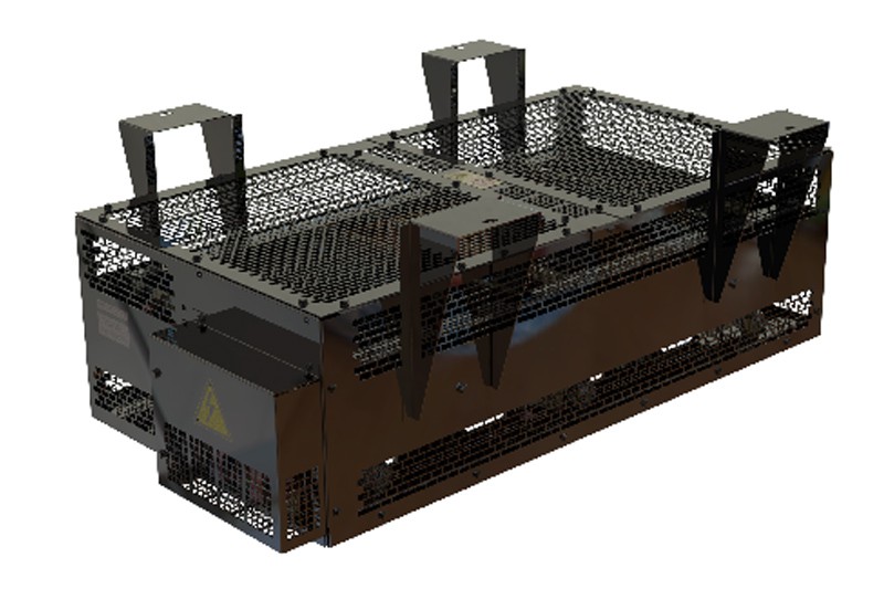
Design of braking resistors mounted under the vehicle
Braking resistors mounted under traction unit are usually designs with horizontal forced cooling. In some cases, resistors with natural cooling are also used, or cooling air is supplied from the outside – e.g. a chopper cooling system.
Such resistor is made of ribbon resistance elements mounted in a duct through which cooling air flows. In most cases, the resistor is also equipped with an additional cooling fan, or it is mounted in the enclosure where the cooling air is supplied from the outside [then the fan is not included in the scope of delivery of the resistor via SIMPAX]. This resistor consists of one or two resistance modules that are connected to the braking chopper. When using two modules, two such resistors are used.

The most important features of the resistor design:
The design resistant to moisture.
Such a resistor is a design with IP20, where active elements of the resistor (being under voltage) are exposed to moisture and pollution. It is made entirely of stainless materials or covered with anti-corrosive layers (copper busbars). It has a hot air outlet orientation system
Vibration resistant design:
The individual connections of the resistor design parts are made with screw connections (no welding), which pays special attention to the appropriate selection of the screw connection type and the tightening torques.
This solution guarantees that the connections will not be unscrewed while operating on the vehicle. Additionally, for the prototype resistors, vibration resistance tests are carried out in accordance with the EN-61373 standard
Resistors equipped with a cooling fan have in some cases elements welded to the fan structure (e.g. mounting eyes). They are then compliant with the EN-15085 standard, Class CP-C2
The design is resistant to high temperatures.
The resistance elements of the resistors warm up during operation up to temperatures around 600°C, which causes their elongation and the possibility of contact with each other and, as a consequence, internal short-circuits of a resistor. Therefore, the design of SIMPAX resistors is made in such a way as to compensate for the thermal expansion of the steel. Resistor enclosures are made of stainless steel resistant to high temperatures.
Its design includes the following aspects:
- the most efficient air exchange possible, resulting in better cooling of the resistor using resistance elements that cause low resistance to cooling air flow
- protection against heating of elements located directly behind the resistor while the vehicle is moving – the heat is discharged in a given direction, e.g. downwards.
- application of efficient cooling fans compliant with railway standards. Thanks to this, the resistance segment can have smaller dimensions than in case of natural cooling.
- outputting resistor connection terminals to a place where there are no high temperatures
Technical parameters of the braking resistor mounted under the traction unit
|
Number of modules: |
Specify Standard 1 or 2 |
|
|
Rated resistance: Rn |
Specify |
[Ω] +7%/-5% according to EN-60322 |
|
Permissible minimum resistance at minimum operating temperature: Rmin |
Specify |
[Ω] It cannot fall below the value causing a higher braking current than the max. chopper current |
|
Permissible maximum resistance – hot resistor |
Specify. Standard Rn + 35% – 40% |
[Ω] It cannot rise above the value causing too little braking resistor power |
|
Rated energy released during braking in the worst case scenario |
Specify |
[J] |
|
Rated braking power or rated continuous power |
Specify |
[kW] |
|
Rated work cycle |
Please specify Xs.operation. Xs.break |
|
|
Rated operating voltage Un |
Specify |
[V] EN-50163 |
|
Peak voltage |
Specify |
[V] Occurs, for example, during emergency braking |
|
Pollution degree |
PD4 |
In accordance with EN-50124-1 |
|
Overvoltage category |
OV2 |
In accordance with EN-50124-1 |
|
Rated insulation voltage: Unm |
Depends on Un |
In accordance with EN-50124-1 |
|
Impulse voltage: Uni |
Depends on Un, PD, OV |
In accordance with EN-50124-1 |
|
Insulation test voltage |
ZDepends on Un |
In accordance with EN-60322 |
|
IP rating: |
IP20 |
For the enclosure and the junction box |
|
Cooling type |
Natural |
|
|
Maximum resistor temperature |
Standard 600˚C |
|
|
Maximum instantaneous resistor temperature |
Standard 800˚C |
In emergency situations |
|
Permissible resistor dimensions: |
Specify |
|
|
Operating conditions |
||
|
Ambient temperature |
Specify |
Standard: -25˚C; 40˚C |
|
Max operating altitude a.s.l. |
Specify |
Standard < 1000m n.p.m. |
|
Shock and vibration |
Cat. 1 / Class A all directions |
In accordance with EN-61373 |
|
Permissible load of top of the resistor enclosure (the ability to walk on the enclosure) |
Specify Standard 0 kg |
No entry on the resistor enclosure |
|
Environment corrosivity category |
C5-I |
In accordance with ISO12944-2 |
|
Other |
||
|
Maximum temperature under the resistor |
Standard < 80˚C |
|
|
Sound power level |
≤70dB |
In accordance with IEC 60076-10 at 1 m distance |
|
Flammability category |
A1 |
all materials used in the resistor design are non-flammable |
Types of resistor testing
S – standard, O – option, N – not applicable
|
Type of test |
Type test (for the prototype) |
Routine tests (each unit) |
Standard |
|
Visual inspection |
S |
S |
EN61287-1 |
|
Dimensional verification |
S |
S |
EN 61287-1 |
|
Resistor mass verification |
S |
O |
EN 61287-1 |
|
Resistor marking verification |
S |
S |
EN 61287-1 |
|
Resistor resistance measurement |
S |
S |
EN 60322 |
|
Inductance measurement |
S |
O |
EN 60322 |
|
Resistor temperature increase measurement (test under load) |
O / S |
N |
EN 60322 |
|
Shock and vibration test |
O / S |
N |
EN 61373 |
|
Insulation test |
S |
S |
EN 60322 |
|
Rain exposure test |
O |
N |
EN 60322 |
|
Other types of tests on request |
O |
O |
Applied Standards:
- EN-60322:2011 / Railway applications - Electric equipment for rolling stock - Rules for power resistors of open construction
- EN-50124-1:2006 / Railway applications - Insulation coordination - Part 1: Basic requirements - Clearances and creepage distances for all electrical and electronic equipment
- EN-61373:2011 / Railway applications - Rolling Stock Equipment - Shock And Vibration Tests
- EN-60077:2018 / Railway applications - Electric equipment for rolling stock - Part 1: General service conditions and general rules
- EN-60529:2003 / Degrees of protection provided by enclosures (IP code)